
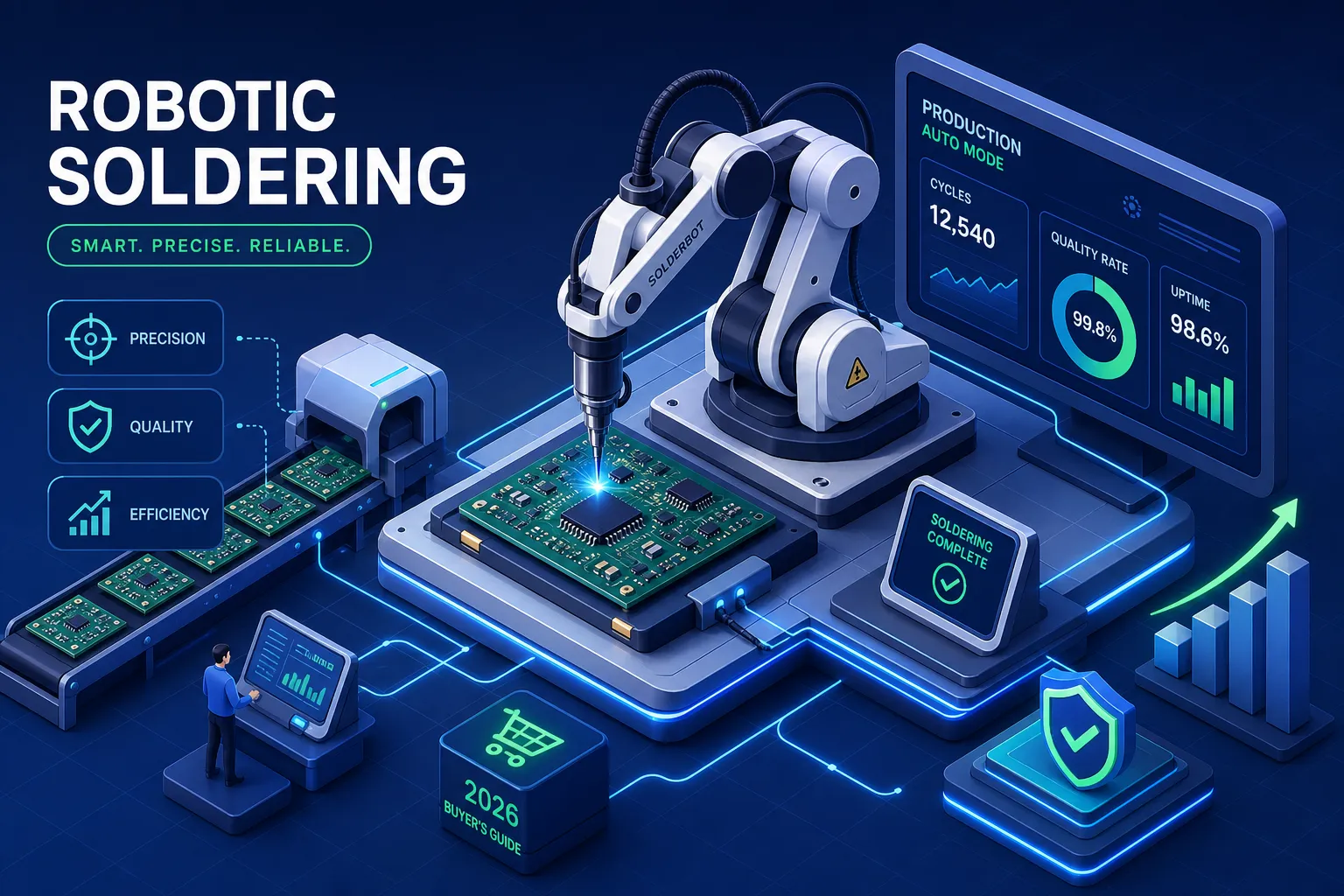
Manual soldering is one of the most variable steps in PCB assembly. Every technician brings a different touch, every shift brings a different tip condition, and every hour brings a different level of fatigue. At low volumes, that variability is manageable. At production scale, it compounds into a defect and rework problem that quietly erodes margin on every board you ship.
This guide to robotic soldering electronics helps you evaluate whether automation makes sense for your operation. You’ll find a clear breakdown of the three main technology types, a practical framework for matching them to your board design, 2026 price tiers, ROI benchmarks from published data, and a cell-build checklist. Leading contract manufacturers have already deployed robotic soldering systems and tracked measurable defect rate reductions across high-mix production lines, which confirms that the technology is production-mature, not experimental. Amtech operates in this space and brings that same validated capability to client programs.
The scope covers selective soldering robots, automated wave systems, and laser soldering. By the end, you’ll have what you need to make a confident sourcing or partnership decision.
Why Manual Soldering Fails at Production Scale
This isn’t a skill problem. It’s a systemic one. Manual soldering results are governed by variables that shift constantly: tip temperature drift, iron calibration, solder wire feed rate, dwell time, technician fatigue, and ergonomic position. None of those variables are locked in, and none of them stay constant across an eight-hour shift or a 1,000-unit run.
The downstream cost of that variability is where the real damage shows up. Defects caught at in-circuit test or functional test require rework labor that can easily cost more than the original assembly. Defects caught in the field are worse: rework on a fielded PCBA risks board integrity and damages customer relationships that take years to rebuild.
Robotic soldering electronics solutions change the equation by locking in the recipe. Each joint gets a programmed tip temperature, a defined contact time, a calibrated solder feed volume, and a fixed motion path. The system executes that recipe the same way on joint one and joint ten thousand. That consistency is where yield improvements come from. IPC benchmark data and selective soldering OEM case studies back this up: manufacturers switching from manual to robotic soldering have reported defect reductions ranging from 80% to over 97%, with process time savings near 50%. One documented example showed staffing drop from five manual operators to a single supervising technician.
The Three Main Types of Robotic Soldering Technology
There are three categories of robotic soldering equipment, and they don’t compete with each other. They solve different problems. Choosing the wrong category for your board design is the most common sourcing mistake in this space.
Selective Soldering Robots
Selective soldering robots target individual joints or defined zones on a PCB. They’re built for mixed-technology assemblies where you have through-hole components on a board that also carries SMT parts. You can’t run that board through a full wave solder machine without thermally stressing the surface-mount components, so selective soldering gives you joint-level precision with a programmable recipe per point. Temperature, solder wire feed rate, contact duration, and motion path are all defined in software and repeatable to a very tight tolerance. This is the most flexible category for high-mix production environments and the most common entry point for robotic soldering electronics programs.
Wave Soldering Robots and Automated Wave Systems
A robotic wave setup isn’t the same as a traditional wave solder machine. The distinction matters. Traditional wave machines run boards through a solder wave with manual setup and pallet loading. Robotic wave systems automate board handling, pallet loading, and flux management, which improves throughput and removes operator-dependent variation from the process. The constraint is that wave soldering isn’t selective: your board design has to be compatible with full-wave processing, meaning SMT components need to be protected or absent from the wave-exposed side. For high-volume, through-hole-dominant boards with consistent layouts, robotic wave automation delivers fast cycle times and excellent repeatability. For mixed-technology or design-variable boards, it isn’t the right tool.
Laser Soldering Systems
Laser soldering uses a focused laser beam to reflow solder at the joint without physical tip contact. That non-contact approach is what makes it valuable for fine-pitch SMT joints, flex circuits, optical components, and any situation where a physical soldering tip can’t reach the joint without risking collateral damage to adjacent parts. Laser soldering confines heat very precisely to the target area, minimizing thermal stress on surrounding components. The capital cost is higher than selective or wave systems, and process tuning is more demanding. For specific design challenges where contact soldering creates real risk, laser is the right answer. It’s a targeted tool, not a universal replacement.
Matching the Technology to Your PCB Design
Technology selection follows from board design and production context. There’s no universal answer, but there are clear signals.
Selective soldering is the right call when your board carries through-hole components alongside SMT parts, when you have temperature-sensitive neighbors within reach of a solder joint, or when your production mix is high and variant counts are changing regularly. Selective robots are programmable per product, so one system handles many board types without re-fixturing the entire line. High-mix operations benefit most here.
Wave soldering automation earns its keep on high-volume, through-hole-dominant boards with stable layouts that don’t change frequently. The design has to support it, but when it does, the throughput and consistency gains are significant. Wave automation doesn’t flex well across design variants, so it’s best when your product is mature and volumes are meaningful.
Laser soldering justifies its cost premium when the joint is fine-pitch, heat-sensitive, or physically inaccessible to a tip. It’s also the answer when zero mechanical stress on the joint is a hard requirement, such as with optical or precision flex assemblies. If you’re evaluating laser soldering for a board that a well-programmed selective robot could handle cleanly, the capital outlay isn’t justified. Use it where contact soldering creates real risk.
Robotic Soldering Electronics: Specs That Predict Real-World Performance
When you’re evaluating robotic soldering equipment, vendor marketing will tell you everything except what matters. Focus on these specifications during any demo or RFQ process.
Repeatability is the most important number. Look for ±0.01, 0.02 mm on precision systems. The I.C.T SR530 delivers ±0.02 mm repeatability and handles boards up to 300 × 300 mm, which covers a wide range of consumer and industrial PCBs. The Hakko HU-200 Series holds ±0.01 mm, suited for tighter-tolerance work. Beyond repeatability, evaluate tip temperature control stability, solder wire feeder calibration, and maximum PCB work envelope. A machine with a large work envelope but inconsistent temperature control will produce variable joints regardless of how well the motion path is programmed.
Vision-guided soldering adds camera-based alignment that compensates for board-to-board positional variation using fiducial marks or joint features. For high-mix environments or boards with lower fixture tolerances, vision guidance prevents positional error from accumulating across a batch. Not every application needs it, but for complex assemblies it’s an important safeguard. Thermaltronics offers integrated camera views covering the full board work area, and KINGSING includes CCD vision systems for positioning and quality control.
The established manufacturers in this space include I.C.T, Japan Unix, Hakko, Thermaltronics, Apollo Seiko, and KINGSING. Before committing to any soldering robot for PCBs, request a process trial using your actual board design. A machine that performs well on a demo board may behave differently on your specific layout, thermal mass, and component mix.
Robotic Soldering Electronics: Costs in 2026 and When You’ll Break Even
Price ranges break into three tiers in the current market. Entry-level benchtop or standalone robotic soldering machines run $2,000, $8,000. Mid-range gantry or automated production systems land at $10,000, $25,000. Enterprise and industrial cells, including fully integrated SCARA or 6-axis systems with vision, safety enclosures, and network connectivity, run $30,000, $100,000 and above. A branded premium system like the Hakko HU-200 lists around $30,900 as a standalone unit, which illustrates why a complete cell always costs more than the base machine price.
Published industry data puts payback at 9, 18 months for most mid-volume selective soldering deployments. One well-documented case study landed at 12.6 months with a single retained technician handling load, unload, and inspection. Labor-hour savings typically run 50, 70%, with total soldering cost per board dropping 40, 65%. A representative benchmark figure from selective soldering OEM data shows a process time reduction from 87.5 hours to 44 hours for the same workload, a 49.7% productivity gain.
The costs buyers most commonly underestimate are programming time, board-specific fixturing, process validation runs, fume extraction, safety enclosure fabrication, and annual maintenance contracts. These line items add 20, 40% to the base machine cost in most real deployments and need to be in your business case from the start. Skipping them in the budget and discovering them during integration is how ROI projections fall apart.
Building Your Robotic Soldering Cell: What’s Required and When to Outsource
A compliant robotic soldering cell is more than a robot arm. A complete cell requires the following components working together:
- Robot arm and motion controller
- Soldering end-effector with integrated tip temperature control
- Automatic solder wire feeder with calibrated feed rate
- Tip cleaning station
- Vision system for board alignment and fiducial recognition
- PCB fixtures and jigs for repeatable part positioning
- Fume extraction and ventilation per IPC and supplier requirements
- Safety enclosure with interlocked access gates and emergency stops
Optional but common additions include nitrogen assist to improve wetting, a preheat stage for high-thermal-mass assemblies, and process calibration tools for periodic validation. The nitrogen and preheat stages are especially relevant for lead-free processes on boards with ground planes or heavy copper pours.
Before sourcing soldering automation for electronics, answer three questions honestly. What is your actual board mix and annual volume? Do you have engineering resources in-house to program, validate, and maintain the cell? Can your facility support the enclosure footprint and ventilation requirements? The answers determine whether a $15,000 mid-range system is the right buy or whether you need a $70,000 integrated cell with full programming support.
For companies running high-mix, lower-volume programs, or those mid-product-launch, building and qualifying an in-house robotic soldering cell is often slower and more expensive than the initial business case suggests. Amtech has already absorbed that integration cost, developed the process recipes, and validated the cell across production programs. Your boards can enter a proven robotic soldering environment without a capital commitment or a six-month qualification cycle, which is a meaningful time-to-market advantage when your product launch is on a deadline.
Choosing Robotic Soldering Electronics: Making the Call
Robotic soldering electronics is no longer a capability reserved for high-volume Tier 1 facilities. The technology is mature, the ROI data is documented, and the price tiers now support mid-market operations with realistic payback timelines. Technology selection, whether selective, wave, or laser, follows from your board design. Machine selection follows from your specs, budget, and whether your team can integrate and sustain the cell without outside support.
If building in-house makes sense for your operation, you now have a component checklist, a price range, and the specs that predict real-world performance. If it doesn’t, the faster path to the same yield improvements is partnering with a contract manufacturer that has already done the integration work and is running robotic soldering across live production programs.
Either path leads to the same result: fewer defects, lower rework costs, and a more consistent assembly process. It remains one of the highest-impact process investments available to a PCB assembly operation. The question is simply which path gets you there fastest.