
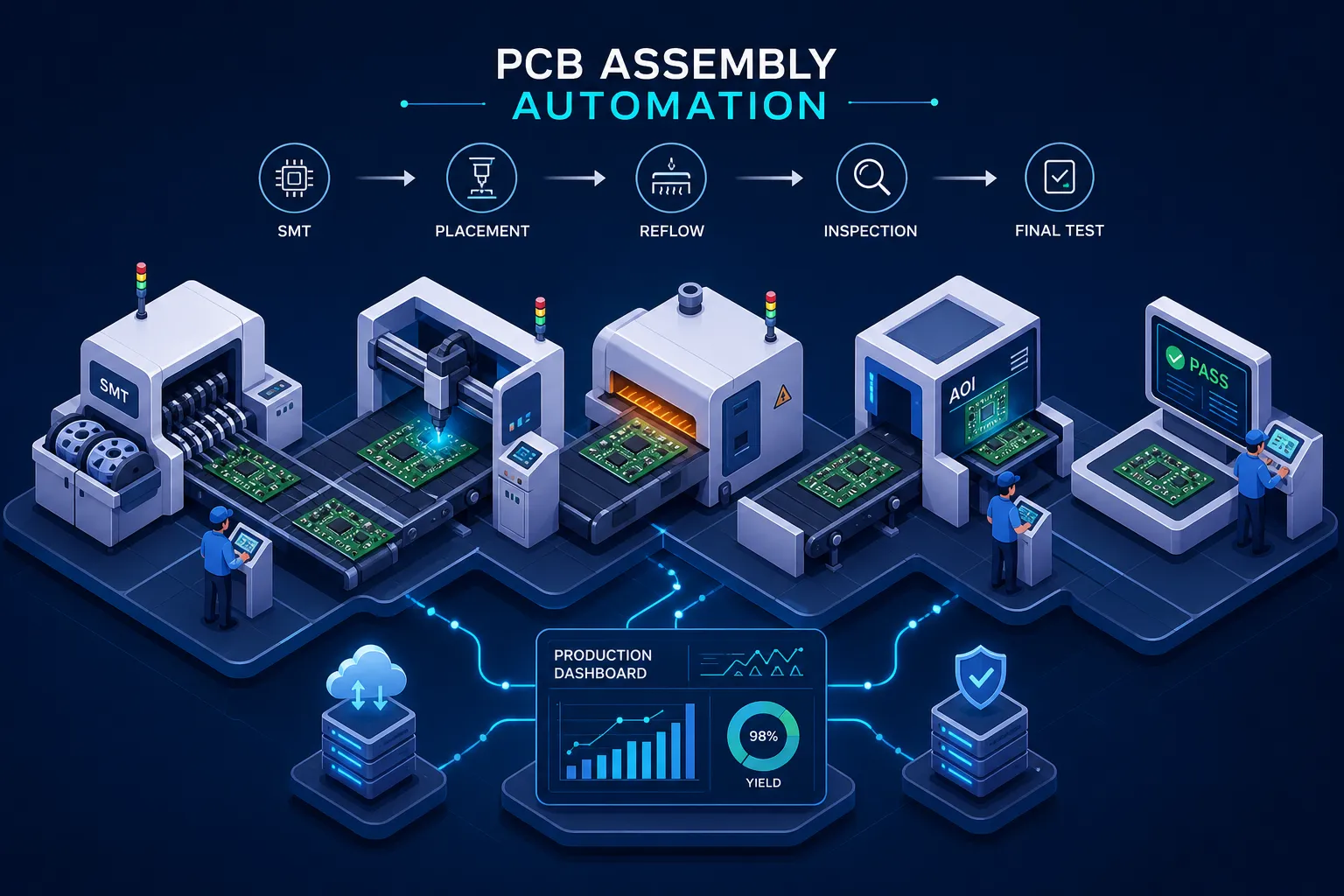
PCB assembly automation replaces the fundamental limits of manual production, not because assemblers are careless, but because human hands and eyes weren’t built for placing 0402 resistors at 20,000 components per hour, holding placement tolerances of ±20 to 50 µm across a thousand boards, or catching a misaligned pad on a 12-layer HDI board under standard lighting. That gap between what manual assembly can deliver and what automated lines consistently achieve keeps widening, and the difference shows up in defect rates, throughput, and long-term program costs.
PCB assembly automation isn’t a single machine you buy and bolt to the floor. It’s a coordinated system of equipment and software working in sequence: paste printer, solder paste inspector, pick-and-place, reflow oven, automated optical inspector, and functional test, with each stage feeding validated, controlled output into the next. The real performance gains come from eliminating human variability at every handoff point, not just the most visible ones.
Some contract manufacturers have pushed this further than standard commercial SMT equipment allows. Amtech has invested in automation and engineering infrastructure developed specifically for the product mix and program types the facility actually runs. The goal is an intelligent production environment where inspection data closes the loop on process decisions in real time. What follows is a stage-by-stage breakdown of what each automation layer does, what it delivers, where complexity enters the picture, and what questions to ask when evaluating a contract manufacturer’s automation depth.
What PCB Assembly Automation Actually Covers
The standard SMT line follows a defined sequence: solder paste printing, solder paste inspection (SPI), pick-and-place component placement, reflow soldering, automated optical inspection (AOI), and functional or automated testing. Each step depends on the one before it. A poorly printed paste deposit that clears SPI will create a bridged joint after reflow. A placement error that slips past AOI shows up as a field failure months later.
Automation’s compounding value comes from the handoffs. When SPI catches a paste volume defect before a single component is placed, the fix costs almost nothing. When AOI data feeds back into printer settings in real time, you’re not just inspecting boards, you’re correcting the process. Manual assembly can’t replicate that feedback architecture regardless of operator skill.
The performance gap between manual and automated SMT is structural, not marginal. Manual assembly defect rates typically run 5 to 10 percent, while automated SMT lines routinely achieve 0.1 to 0.5 percent. That delta isn’t about effort; it’s about the fundamental difference between human consistency and process consistency across thousands of boards.
PCB Assembly Automation: Core Equipment on the SMT Line
Solder paste inspection and pick-and-place: the front half of the line
SPI is the first quality gate in any automated SMT line. Before a component touches the board, SPI measures paste deposit volume, height, position, and coverage at every pad. A printing error caught here costs a few seconds of squeegee time to correct. The same error caught after reflow means rework or scrap, and on a dense board, rework is rarely clean.
Pick-and-place machines are the throughput engine of the SMT line. Robotic arms equipped with vision systems pull components from feeders and tape reels, verify component orientation and identity, and place them with high-precision accuracy in the ±20 to 50 µm range typical of modern platforms. Mid-range systems handle roughly 10,000 to 30,000 components per hour; high-end systems exceed 50,000 CPH on rated benchmarks, with real-world production typically landing between 35,000 and 75,000 CPH depending on component mix. Machine programming draws from Gerber files, CAD data, and the BOM. Standardized interfaces like IPC-HERMES-9852 allow program data and board identity to move with the PCB through the line automatically, eliminating manual program selection and the errors that come with it.
Reflow soldering and AOI: closing the loop
The reflow oven converts paste deposits into permanent solder joints. Boards travel on a conveyor through controlled temperature zones: preheat, soak, reflow peak, and cooling. The thermal profile must match the solder paste specification and respect the thermal limits of every component on the board. Deviations produce cold joints, voiding, component damage, or delamination. Profile engineering is not optional; it’s part of the process design.
AOI systems scan the assembled board post-reflow using high-resolution cameras and inspection software. They flag missing components, misaligned parts, solder bridges, tombstoned passives, insufficient solder, and other visible defects against acceptance criteria defined by IPC-A-610H. In a properly integrated line, AOI data doesn’t just populate a quality record, it feeds back into upstream process adjustments and provides the traceability data that compliance-sensitive customers require.
What PCB Assembly Automation Delivers in Quality, Throughput, and Cost
Throughput and defect rate improvements manufacturers actually report
The numbers manufacturers report after automating are consistent. Throughput gains of 30 to 50 percent over manual baselines are common. In one documented solder robot deployment, annualized output increased from 24,855 PCBs to 49,560 PCBs, a 99.4 percent increase in units produced on a single installation. On complex HDI boards, one 2026 program tracked defect rates dropping from 120 DPMO to 42 DPMO within six months, with first-pass yield improving from 91 to 96 percent.
The downstream effect on field failures is significant. Industry analyses of automated test and inspection implementations cite 40 to 70 percent reductions in field failure rates as a consistent outcome. Fewer defects at the board level mean less rework labor, less scrap material, and fewer warranty claims. The cost savings aren’t front-loaded into the capital purchase; they accumulate across every production run.
What this means for the customer and the business case
From the customer’s side, a well-automated contract manufacturer translates to shorter lead times, more consistent board quality, and better traceability for regulatory or compliance submissions. For industrial, automotive, and defense-adjacent programs, board-level traceability isn’t a nice-to-have; it’s a program requirement.
Payback periods for PCB assembly automation typically run 8 to 24 months, depending on volume and application. Pick-and-place and collaborative robot applications tend toward the faster end of that range, often 6 to 18 months. Test automation and full dedicated lines run toward 12 to 24 months. The inputs that drive faster payback are higher volume, more shift utilization, and applications where automation displaces significant manual labor.
Where Mixed-Technology Boards Complicate the Automation Picture
Partitioning SMT and through-hole for automated processing
Mixed-technology boards, those carrying both SMT components and through-hole parts, require a more deliberate process architecture. The core principle is to keep SMT parts grouped for reflow-based processing and reserve through-hole positions for connectors, large passives, and components that require mechanical strength or higher current handling. Maintaining at least 2.5 mm clearance between SMT and PTH components reduces interference during downstream soldering operations.
Three process options handle the through-hole side of a mixed board: pin-in-paste (PIP), selective wave soldering, and solder preforms. PIP embeds the through-hole soldering into the SMT reflow process and delivers high throughput on boards with limited PTH requirements. Selective wave soldering lets you solder through-hole sections without exposing the entire board to a wave, which protects nearby SMT joints. Each option carries different throughput, yield, and design implications, and the right choice depends on board layout, component mix, and volume.
Protecting quality with in-line inspection at every transition
Mixed-technology lines need more inspection stages, not fewer. SPI runs before reflow to catch paste defects before components are seated. AOI runs after placement and again after reflow, catching defects introduced at each thermal stage. Through-hole joints receive process-appropriate inspection, visual, X-ray, or functional test, based on joint criticality and application requirements. Each additional inspection gate is a feedback opportunity, not just a pass/fail checkpoint.
The most effective quality lever on a mixed-technology board is DFM, not inspection. Footprint design, lead planarity, pad geometry, and board segmentation by process type determine whether defects are avoidable in the first place. A board designed for its manufacturing process will run cleaner at every stage than one optimized purely for electrical performance and handed to manufacturing to sort out.
The Software Layer: Making PCB Assembly Automation Intelligent
SMT programming and machine-to-machine communication
SMT programming software converts PCB design data, Gerber files, CAD outputs, and the BOM, into machine programs for the printer, pick-and-place, and line equipment. Standardized interfaces like IPC-HERMES-9852 allow program data and board identity to move with the PCB through the line automatically, eliminating manual program selection and the operator errors that come with it.
MES software sits above the line to manage production execution: material tracking, WIP status, operator actions, process genealogy, and board-level traceability. In a fully integrated environment, MES connects to customer systems to support order-level traceability and compliance reporting. That integration is what separates a bare SMT line from one with full production intelligence.
AI-assisted inspection and closed-loop process feedback
Traditional rule-based AOI compares features against fixed thresholds around a golden reference image. It’s fast but brittle: lighting changes, component lot variation, and normal process drift all trigger false calls. AI-assisted inspection systems use machine learning models trained on real defect libraries. They learn the distribution of acceptable appearances instead of enforcing rigid thresholds, which reduces false positive rates by 20 to 40 percent in deployed systems, with well-trained models reaching under 1 percent false call rates.
Closed-loop feedback is what separates a modern automated SMT line from a collection of individual machines. When SPI and AOI data feed back into line control software, the system adjusts printer parameters or flags placement anomalies in real time, before a batch of boards moves further down the line. That’s not inspection anymore; it’s process control, and it’s where the largest sustained yield improvements come from.
What Strong PCB Assembly Automation Capability Looks Like in a Contract Manufacturer
Beyond standard SMT equipment: process intelligence and purpose-built automation
Most contract manufacturers run standard commercial SMT equipment. The real differentiator is how deeply automation is embedded into the full process, including custom fixtures, purpose-built tooling, and software configured specifically for the product mix the manufacturer actually runs. Off-the-shelf equipment gets you into the game; purpose-built automation is what sustains performance at high mix and changing volume.
Amtech has invested in automation and engineering resources developed internally, with tools designed to reduce manual intervention, improve yield, and support high-mix production without sacrificing throughput. That investment reflects a view that automation is a living capability, not a one-time capital purchase. The production environment needs to evolve with the product programs it supports, and that requires engineering resources committed to automation development, not just equipment operation.
Questions to ask when evaluating a contract manufacturer’s automation depth
When evaluating a contract manufacturer’s automation capability, the right questions cut through equipment lists quickly. Ask what inspection systems are in-line versus end-of-line. Ask whether their MES provides board-level traceability and whether that data is accessible to you. Ask whether they can show AOI and first-pass yield data for programs similar to yours in complexity. Ask how they handle mixed-technology boards and what their selective soldering setup looks like. Ask what functional test coverage looks like for your specific product type.
Automation is not binary. Every contract manufacturer can say they have pick-and-place and AOI. The meaningful evaluation is about depth: how inspection data connects to process decisions, how the software layer provides traceability, and whether the manufacturer treats automation as a competitive investment or a commodity line item.
Putting It Together
PCB assembly automation is a system-level discipline. Every stage from SPI through functional test plays a role in quality, throughput, and cost outcomes, and the gains compound when the stages are integrated through software that closes the feedback loop. The data is consistent: manufacturers who automate well see measurable defect reduction, throughput gains, and payback periods that often arrive faster than projected.
Whether you’re building an in-house line or evaluating a contract manufacturing partner, the core questions are the same: how deep does the automation go, is the software layer genuinely closed-loop, and does the line data give you board-level traceability? Those questions separate production environments that deliver consistent quality from ones that depend on operator attention to compensate for process gaps.
Amtech is built to support programs from early-stage DFM through high-volume production, with the automation depth and engineering infrastructure to back it up. If that matches what your program requires, the conversation is worth having.